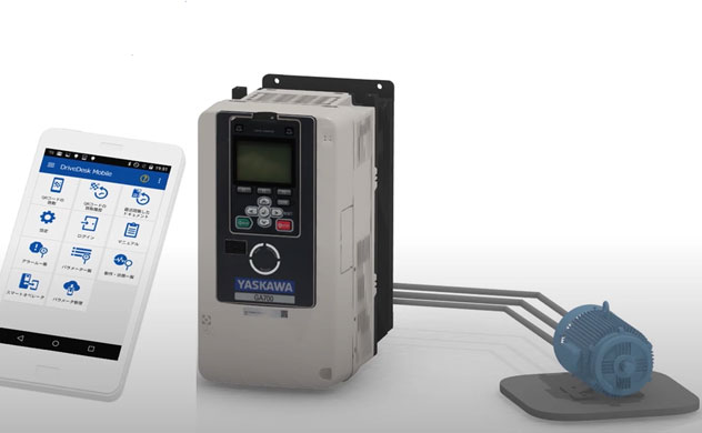


Main Player in Variable Speed Driving
How does an AC drive (inverter) change a speed of motors?
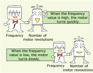
To change the motor speed, that is the number of revolutions, AC Drive (inverter) makes the frequency (Hz) to motors change. The higher the frequency value, the faster the motor will rotate, and the lower the frequency value, the slower motor will rotate.
The AC Drive (inverter) enables variable speed operation by changing the frequency.
By the way, what did the AC Drives (inverters) effect to generate a wide range of frequencies from the rated commercial power supply?
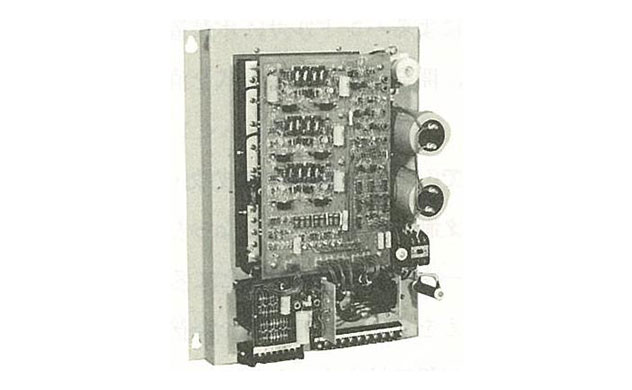
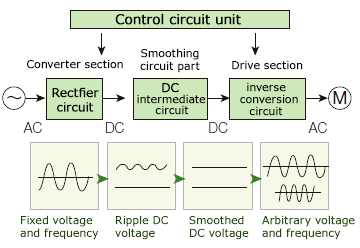
The AC Drive’s power conversion circuit consists of 1) A rectifier circuit, 2) An intermediate circuit, and 3) An inverse conversion circuit. The AC Drives (inverters) converts AC voltage to DC voltage with a rectifier circuit, and it smooths the DC voltage with a DC intermediate circuit. Then, the smoothed DC voltage is converted to an arbitrary AC voltage as well as frequency by a reverse conversion circuit and applied to the motor. Such power conversion is achieved by high-speed switching of power transistors, which are semiconductor devices. The output frequency is different due to the difference in switching control.
Power Conversion Method PAM and PWM
The PAM (pulse amplitude modulation) method and the PWM (pulse width modulation) method are often applied to the power conversion method of the AC Drives (inverters).
PAM controls to change the intensity of frequency. It relatively enables to convert with a low switching frequency, and is widely used in household products such as air conditioners.
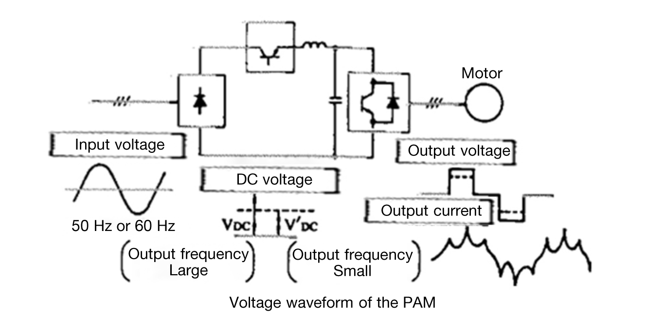
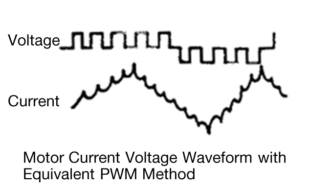
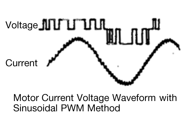
It can be turned on / off instantaneously and converted to three-phase AC, based on a prescribed switching pattern (directed frequency and voltage), so it is widely used in industrial fields that require a wide range of variable speed drive.
AC Drive Control System; V/f Control and Vector Control
There are various types of machines and various movements. Then, how is the frequency outputs from AC Drives (inverters) controlled and suitable motor rotation performed for each machine?
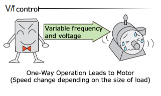
Standard control methods for general-purpose AC Drives (inverters) are split with V/f control and vector control. V/f control is to stabilize the ratio of the voltage (V) and frequency (f) from an AC Drive (inverter). For example, in case of an AC Drive (inverter) with 200V power supply voltage, it outputs 200V at 60Hz and 100V at 30Hz. Because it can use the determined V/f pattern of frequency and voltage, single drive could rotate multiple motors simultaneously.
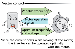
On the other hand, vector control is meant to separate 1) torque current which current becomes torque, and 2) excitation current which generates a magnetic field in the rotor among the currents flowing to the motor, and control the direction of the motor current with vector calculates. Since the current that flows in accordance with the motor’s characteristics can be supplied, it enables to perform accurate operation with less error.
“Slip” To Be Required to Rotate the Induction Motor
How do you use V/f control and vector control separately? Before explaining the features of AC Drive (inverter) control, let’s briefly move on the brief explanation of “slip” of the motor. The rotation of the induction motor requires something called a “slip”. “Slip” is the delay of the rotational frequency of “the rotor” relative to the rotational frequency of “the stator”. The rotational speed of the induction motor uses the electromagnetic force generated between the stator and the rotor, so torque merely can generate with this “slip”. The larger the motor load, the larger the “slip” and the larger the rotational speed delay.
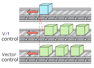
In vector control, the status of “slip” is calculated in real time and added to the motor, so that the rotational speed of the motor can be constant speed control without changing with the size of the load. The example case of conveyor below shows V/f control causes a change in conveyor speed depending on whether or not the load is on. Vector control allows constant speed control regardless of the weight of the package.
Features and Applications from the Viewpoint of Control Performance
AC Drive (inverter) control performance can be determined from indicators such as low-speed torque, speed control range, and speed control accuracy. In low-speed operation, when the load increases, the “slip” also increases and the motor speed decreases.
In V/f control, the motor stops in some cases. With vector control, large torque can be generated, enabling operation without stopping even at low speed. In terms of speed control range and speed control accuracy, vector control can achieve variable-speed operation with a wider control range and less error than V/f control, because the motor characteristics can be maximized by vector calculation of the motor current.
However, the motor parameters must be set to match the motor characteristics. It is not possible to rotate more than one motor at a time.